
Georeference
What is Georeferencing?
(This option is not available on the Freeware version)Georeferencing is the process of scaling, rotating, translating and deskewing the image to match a particular size and position.
The term georeference will be familiar to GIS users, but general CAD users may have never seen the word before, even though the function is very useful for their work. The word was originally used to describe the process of referencing a map image to a geographic location.
Why is it necessary?
A raster image is made up of pixels and has no particular size. Without georeferencing, the vectorised CAD/GIS drawing size is determined by the raster's pixel dimensions (the width and height of the raster in pixels). This is in turn determined by the image resolution (DPI). This image sizing will usually bear no relationship with the dimensions of the drawing that the raster represents.
- Here is an example:
- You might scan a drawing at 100dpi and get a raster that is 1000 pixels wide by 1000 pixels high, then after vectorisation, the exported DXF drawing will be 1000 units wide by 1000 units high (the units can be set in your CAD system, for instance, metres or inches). Then if you scan the same drawing at 200dpi you will get a raster that is 2000 pixels wide by 2000 pixels high, and the resulting vectorised DXF drawing will be 2000 units wide by 2000 units high. In both cases the vectorised drawing is from the same original, but you get two different sized DXF drawings depending on the scanning resolution. In addition, it is likely that neither DXF drawing is the size that you actually wanted it to be.
Whereas a raster drawing has no particular scale, a vector drawing is normally drawn to a precise scale.
What do I need to do?
The georeference process simply involves selecting a pixel on the raster image and specifying what coordinate it represents for your vector drawing. When you have picked 3 pixels and specified their vector coordinates, WinTopo Pro can calculate the correct mapping for every pixel in the image, and when you load the DXF drawing into your CAD or GIS or CNC system it will automatically be located in the correct position and at the right size.
To get the Georeference option click the Vector menu and select Georeference (Scaling/Offset)...You will see this window:
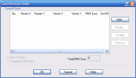
First you should click the Add... button to specify the first Control Point. You will see this window:
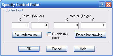
You can type in the X and Y pixel location, but the most common usage is to click the Pick with mouse... button. When clicked, the Control point window will disappear and the cursor will change to a crosshair ![]()
Simply click on the pixel that you want as a Control Point. This should be a feature on the image for which you can identify a specific coordinate location.
- For example:
- On a map or geographic survey, a grid intersection or a survey station would be a good choice. On an engineering drawing it might be one end of a dimensioned length on a line that should be horizontal or vertical (and your 2nd control point will be the other end of the line).
When you click on the pixel it will be marked with a cross symbol ![]() and the Control Point window will reappear, showing the location of the pixel in the Raster X and Y boxes. Now you just need to type in your desired coordinate for this pixel into the Vector X and Y boxes. Then press the OK button and the Georeference window will be shown again, displaying the details of the Control Point.
and the Control Point window will reappear, showing the location of the pixel in the Raster X and Y boxes. Now you just need to type in your desired coordinate for this pixel into the Vector X and Y boxes. Then press the OK button and the Georeference window will be shown again, displaying the details of the Control Point.
You need to Add... at least 3 Control Points so that WinTopo Pro can calculate the correct mathematical image transformation. It is permissible to give just 2 control points, although this will not allow WinTopo to compensate for stretching or skewing of the image.
When you have added your control points, click the OK button to dismiss the Georeference window. As you move the cursor over the image you will see the georeferenced coordinates shown on the status bar at the bottom of the WinTopo Pro main window.
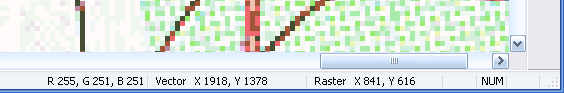
The Raster coordinate shows the location of the pixel which is under the cursor, and the Vector coordinate shows the georeferenced location that it would have in the vector output. You can use the Vector display to verify that that the control points are correct - by moving the mouse to other points on the drawing and quickly checking that they are shown as positioned roughly where you expected them to be. If you mis-entered a control point you will usually see large discrepancies in the Vector positions of other points on the image.
What about more than 3 Control Points?
If you enter more than three control points then you can choose how WinTopo Pro uses them for calculating the georeference transformation. You will notice that the options Best 3 Points and Average of All Points have become available. But first let us explain the RMS Error...
On the Georeference window, each control point has an RMS Error value. RMS stands for Root Mean Square, which refers to a distance. The RMS Error value is the distance of the georeferenced control point from the vector coordinate which you specified for it. When there are 3 control points the RMS Error values are always zero, because WinTopo Pro can calculate an exact mathematical transformation. When there are more than 3 control points then some may show an RMS Error because the georeference calculation is not able to correct for localised deformation of the raster. The RMS Error values will show you which of your control points are likely to be most accurate. You want to have control points with the lowest RMS Error values.
- Best 3 Points
- With this option selected, WinTopo Pro selects which 3 control points to assign with zero RMS Error, such that the remaining points have the minimum Total RMS Error. This is the default setting, because it guarantees that at least 3 of your control points will be precisely positioned on the vector output drawing, and the remaining control points will have minimal inaccuracy.
- Average of All Points
- If you think that all of your control points are equally accurate (or inaccurate!) and no three should be given priority over the others, then select this option. WinTopo will place all the control points near to your specified vector coordinates such that the RMS Error distance is about the same for each point, and the Total RMS Error is minimal.
When you have more than three control points, the RMS Error values will show you which points WinTopo Pro considers to be most accurate. However, you may know which points are actually most accurate and want those to be favoured over the others in the georeference calculations. Therefore you can use the Disable button to prevent a point from being used the calculations. First click the point in the list, so that its Point No. is highlighted, then click the Disable button. The point's On/Off value will be shown as Off rather than On. A disabled point can be easily re-enabled, because when the point is highlighted in the list the button will read Enable rather than Disable.
If you think that the Total RMS Error value is too high, you can experiment with disabling one point at a time to see if the Total RMS Error goes down dramatically for a certain point. This would indicate that the point is either particularly inaccurate, or that you may have entered its position incorrectly.
Up to 200 control points may be added, though in most cases 3 is sufficient.
Saving and Loading Control Points
After Georeferencing your drawing you may wish to save your control point data for later re-use. Click the File menu and select the Save Control Points File As... option. WinTopo Pro will offer a file name which is the same as the raster name, except with a .ctl extention at the end.
To re-use the same control points in WinTopo Pro, first load the raster file, and then select the Load Control Points File... option from the File menu, and pick the file which you previously saved.
Saving the World File
Users of GIS systems will be familiar with the World File that can accompany a raster image. The World File contains the georeference calculation results to enable another system to reproduce the same coordinate transformation.
To save the World File click the File menu and select the Save World File As... option. WinTopo Pro will offer a file name which matches the raster name, but with the world file three-letter extension at the end. By convention, the world file extension is comprised of the first and last letters of the raster file name extension, and the letter w. For example, for a TIFF file image.tif the world file name would be image.tfw, but for a bitmap file image.bmp the world file name would be image.bpw instead.
Related Topics: